Apr 01, 2026
May 29, 2025
May 27, 2025
Apr 14, 2025
B4, Qingdao High-Tech Zone, No. 17 Songyuan Road, Qingdao.
+86 13864822549
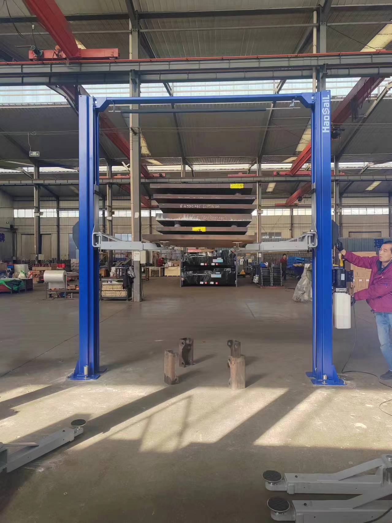
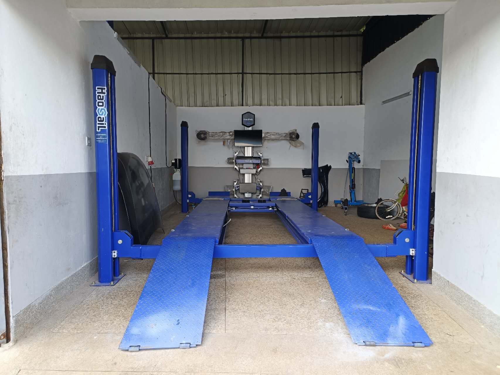
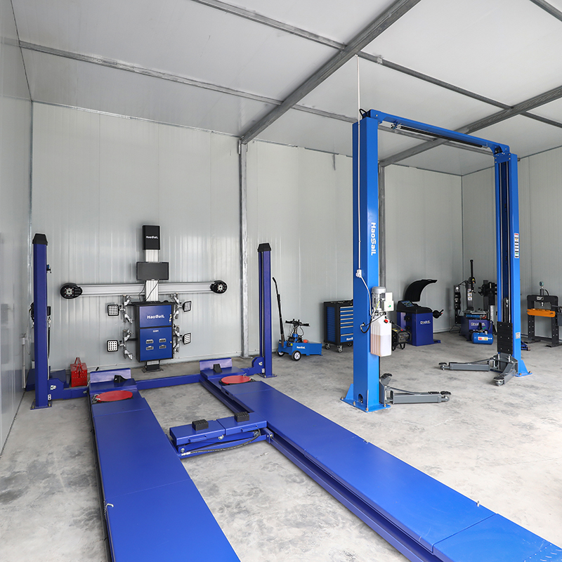
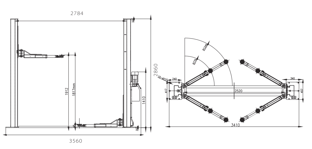
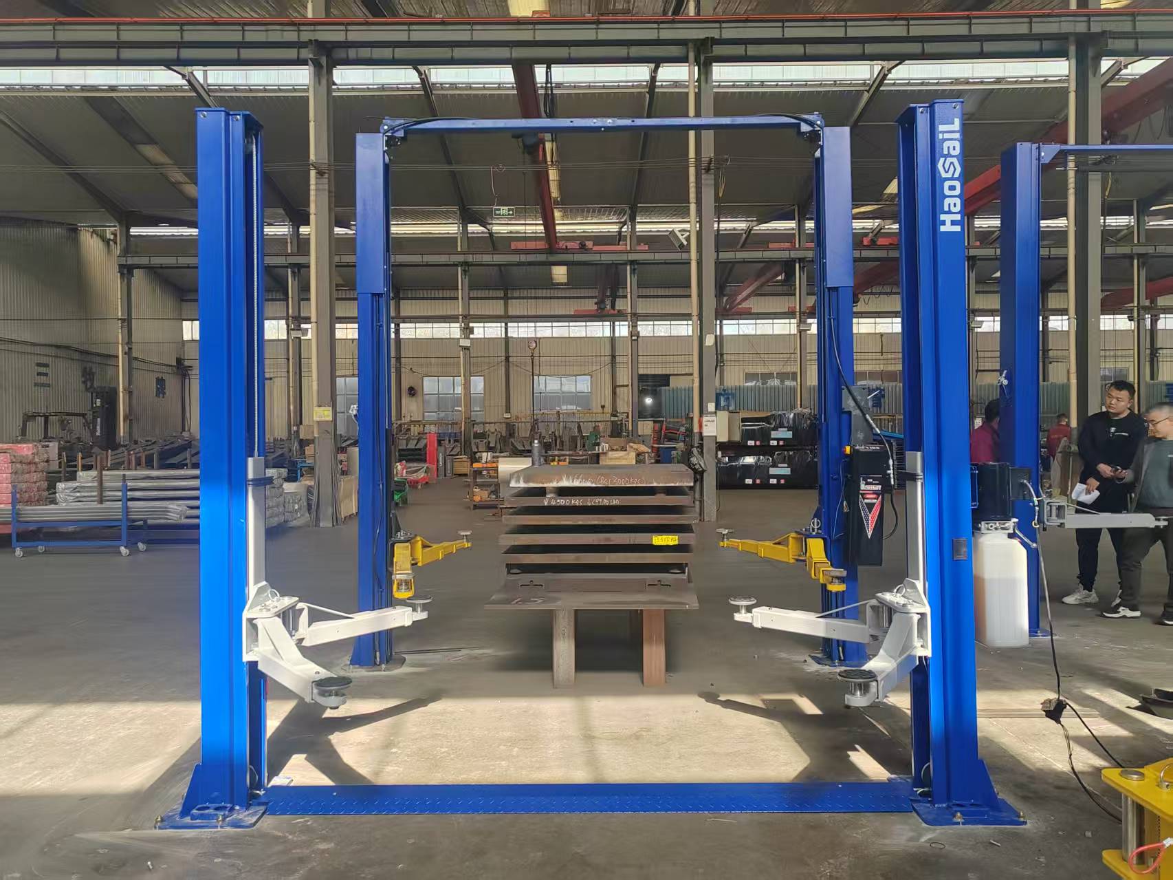
Haosail car lift is a special equipment for the auto maintenance industry, which lifts vehicles (total weight ≤8T) to the specified height through hydraulic drive, providing a safe working space for vehicle maintenance, repair and inspection. The equipment is driven by hydraulic pressure, with the characteristics of stability, safety and strong bearing capacity.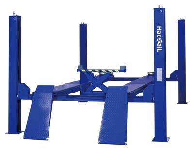
We provide a full range of car lift products to meet different maintenance scenarios:
| Lift Type | Core Models | Lifting Capacity | Lifting Height | Applicable Scenarios |
|---|---|---|---|---|
| 2 Post Car Lift | HCL240AE, HCL240BE | 4T / 4.5T | 1900mm | Conventional vehicle lifting and maintenance |
| Gantry Car Lift | HCL245BS, HCL240BE | 4T / 4.5T | 1900mm | Professional auto repair shop, high-frequency operation |
| 4 Post Car Lift | HCL440B, HCL450B, HCL460B | 4T / 5T / 6T | 1500mm | Wheel alignment, heavy vehicle maintenance |
| Scissor Car Lift | HSL350C, HSL350B, HSL350A, HSL450D | 3T / 3.5T / 4T /5T | 1000mm-2050mm | Quick repair, tire replacement, space-limited workshop |
| Pit Car Lift | HDL420B, HDL420C | 2T | 370mm-450mm | Pit maintenance workshop |
| Motorcycle Lift | HS508A-LST | 800kg | 1200mm | Motorcycle repair |
The motor drives the gear pump to extract hydraulic oil, which is transported to the hydraulic cylinder through the oil pipe. The pressure of the hydraulic oil pushes the piston rod to expand and contract, driving the bearing structure to rise. When descending, the safety lock is unlocked, the solenoid valve is controlled to make the hydraulic oil flow back to the oil tank, and the bearing structure descends smoothly under the action of gravity.
Recommended hydraulic oil: N32 / N46 (scissor lift can use L-HM32/L-HM46)
Press the control button, the contactor is energized, the motor starts to drive the hydraulic system. The limit switch monitors the lifting height, and cuts off the motor power when the upper limit is reached to prevent overload collision. The emergency stop button can quickly cut off the power to ensure safety in emergencies.
| Maintenance Cycle | Core Maintenance Content |
|---|---|
| Daily Maintenance |
1. Clean the equipment surface, remove oil stains and dust 2. Check the engagement state of the safety lock, no broken strands of steel wire rope 3. Check no leakage of hydraulic oil pipes and joints 4. Fasten anchor bolts and connecting bolts 5. Lubricate the swing arm shaft and steel wire rope with lithium-based grease |
| Weekly Maintenance |
1. Check the flexibility of moving parts (swing arm, roller, fixture) 2. Test the function of safety components (limit switch, emergency stop button) 3. Check hydraulic oil level, replenish if necessary 4. Lubricate all sliding surfaces (inner side of column, platform guide rail, scissor frame shaft) |
| Monthly Maintenance |
1. Fully check the fastening of all bolts, especially re-tighten the anchor bolts 2. Check the seals of the hydraulic system, replace if there is leakage 3. Check the wear of lifting pads, swing arms and fixtures 4. Clean the hydraulic oil tank filter with gasoline |
| Half-year Maintenance |
1. Replace the hydraulic oil (first replacement after 6 months of use, then once a year) 2. Clean the hydraulic oil tank and filter, check the wear of gear pump and oil cylinder 3. Adjust the tension of steel wire rope to ensure synchronous lifting 4. Check the verticality of the column and the levelness of the platform, adjust if the deviation exceeds 5mm |
| Annual Maintenance |
1. Fully disassemble and check the wear of wearing parts such as bearings, rollers and pin shafts, replace if necessary 2. Check the insulation layer of motor, contactor and wires, replace if aging 3. Test the sensitivity of safety lock and reliability of limit switch, carry out full load test |
| Fault Phenomenon | Possible Cause | Solution |
|---|---|---|
| Motor does not run |
1. Circuit breaker/thermal relay trips 2. Voltage does not match 3. Loose wiring 4. Limit switch failure 5. Motor coil burned out |
1. Close the circuit breaker or press the reset button of the thermal relay 2. Provide the voltage required by the equipment 3. Re-wire according to the electrical schematic diagram 4. Replace the limit switch 5. Replace the motor |
| Motor runs but cannot lift |
1. Motor reverses 2. Insufficient hydraulic oil 3. Hydraulic pump air intake / suction pipe falls off 4. Down valve body failure 5. Overload 6. Fixture not released |
1. Adjust the wiring to change the motor steering 2. Replenish the corresponding type of hydraulic oil 3. Fasten the suction pipe joint and exhaust 4. Repair or replace the down valve body 5. Reduce the load to the rated value 6. Check and release the fixture |
| Can lift without load, but cannot lift with heavy load |
1. Low voltage 2. Impurities in the down valve body 3. Improper adjustment of safety valve pressure |
1. Stabilize the voltage to the equipment requirements 2. Disassemble and clean the down valve body 3. Adjust the safety valve pressure according to the rated load |
| Slowly descends without pressing the down button |
1. Impurities in the down valve body 2. Hydraulic system leakage |
1. Clean the valve body 2. Check the oil pipes and joints, repair the leakage |
| Lifting and lowering speed is slow |
1. Hydraulic oil mixed with air 2. Loose suction pipe 3. Improper installation of oil return pipe 4. Worn seal of hydraulic pump |
1. Repeatedly lift and lower to exhaust or replace hydraulic oil 2. Fasten the suction pipe 3. Reinstall the oil return pipe 4. Replace the hydraulic pump seal |
| Lifting is not level |
1. Uneven tension of balance steel wire rope 2. Inclined installation ground 3. Deviation of synchronism of master-slave scissor |
1. Adjust the steel wire rope nut to make the tension uniform 2. Level the equipment with gaskets, re-pour the ground if the deviation exceeds 5mm 3. Adjust the hydraulic pressure of the master-slave machine |
 6. Safety Specifications