Aug 25, 2023
May 08, 2023
Nov 11, 2022
Oct 20, 2022
B4, Qingdao High-Tech Zone, No. 17 Songyuan Road, Qingdao.
+86 13884977673
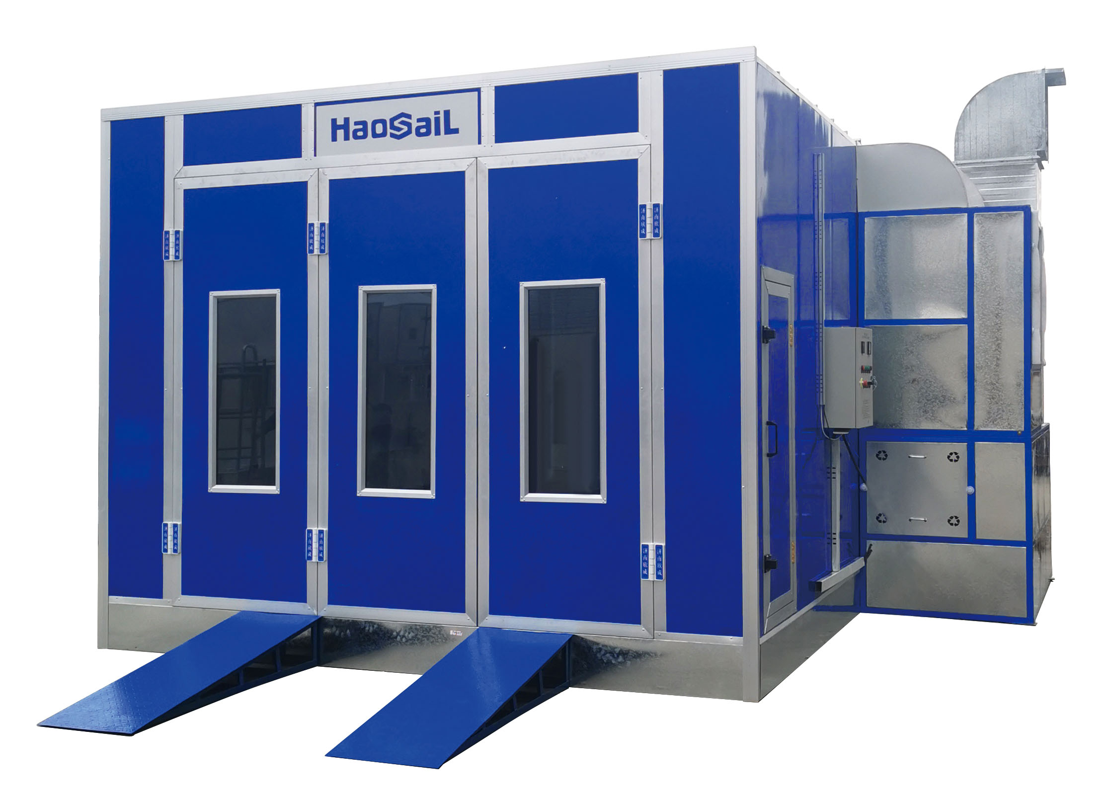
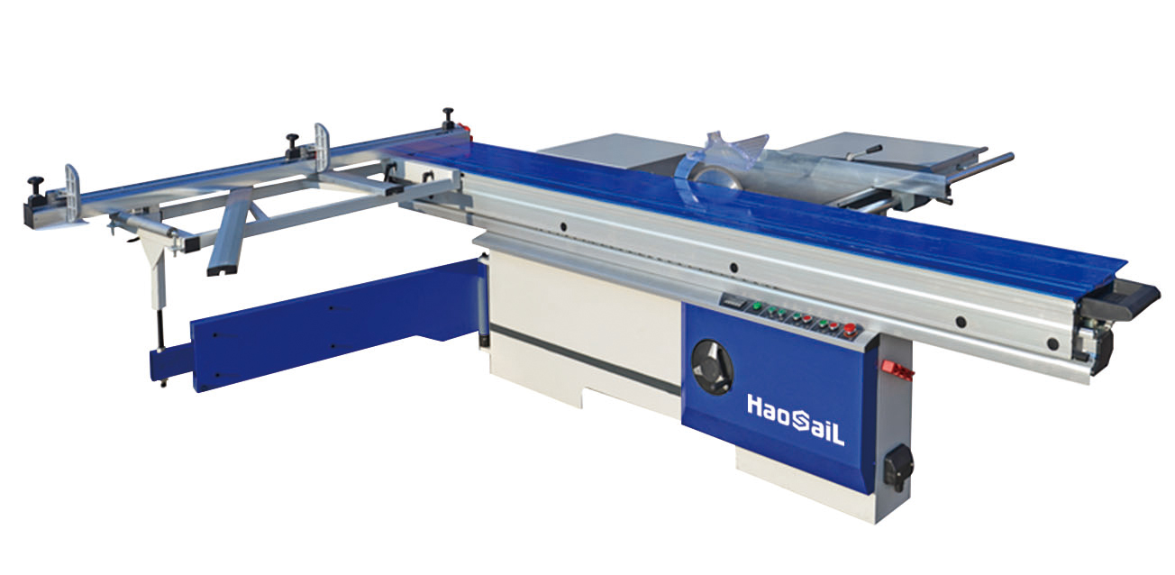
I. Introduction to edge banding machine

The edge banding machine can continuously and automatically complete the conveying, gluing, cutting, front and rear trimming and sealing of workpiece and sealing belt at one time
Lower milling, upper and lower fine milling of fillet edge, scraping, polishing and other processes have become an automatic production line for edge sealing.
A – base: the bearing structure of the machine.
B - distribution box: contains the electrical equipment of the machine.
C - feeding belt: plate feeding.
D - feeding belt feeding gear motor: transfer action to the feeding belt.
E - upper pressure beam: apply necessary pressure to prevent the plate from shifting to the side during processing.
F - feeding side backer: excellent guidance for sheet feeding.
G - feed roller: a device for processing in the length direction. Press the plate close to the side mountain during feeding.
H – oil water filter: filter, which can lubricate and maintain stable air pressure.
J - lubricating oil pump of feeding belt: automatically add oil to lubricate the rubber pad of feeding belt.
K – plate support: support the plate during processing.
L - scale support table: optional device, including a rotatable support, which can be equipped according to processing needs
*Support strip with side roller; Support the plate and use side pressure to ensure stable processing.
2. Adjustment of profiling wheel assembly:
According to the position of the feeding backup plate assembly, determine the adjustment position of the profiling assembly and the end face pre milling allowance, and the operation steps
The steps are as follows: 1. Turn the star handle 1 and adjust the screw rod to drive the left profiling assembly to move. Amount of movement
The size is displayed by the digital meter (every 1mm / turn). Turn the star handle clockwise to increase the pre milling allowance
After the left profiling assembly is adjusted, the adjustment method of the right profiling assembly is the same as that of the left profiling assembly
3. Adjustment of pre milling assembly stroke:
The stroke of the pre milling tool assembly can be adjusted through the adjusting nut, bolt and adjustable pressure oil pressure at the rear end
Shock absorber is used to realize the travel of the advance and retreat knife, so as to ensure that the advance and retreat knife is soft, stable and free of vibration.
Other adjustment methods:
(1) Stroke adjustment of left pre milling tool assembly: it is realized by adjusting the position of limit bolt 3. Rotate clockwise to reduce the stroke. After adjustment, lock the nut.
(2) Stroke adjustment of right pre milling tool assembly: adjust the position of adjustable pressure oil pressure shock absorber (adjusted by general maintenance personnel), rotate clockwise and the stroke decreases.
(3) Adjustment of buffer force of adjustable pressure oil pressure shock absorber: by adjusting the buffer force of oil pressure shock absorber, the right milling cutter assembly can be prevented from colliding with the base plate, ensuring soft and stable feed and reducing vibration. When adjusting, the larger the scale value on the shock absorber, the smaller the buffer force.